2585421 - Introduction - INSTRUMENT PANEL
NQS OPERATION
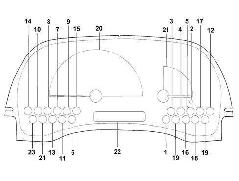
The instrument panel is the component which makes it possible to display the main functional parameters of the vehicle for the driver. This instrument panel includes a CAN interface at low speeds to allow dialogue with other system connectors (e.g. engine management control unit, dashboard connector, ...).The instrument panel is available in four versions and these panels have a printed circuit.The instrument panels SHOULD NOT be dismantled in the service network because their assembly requires precision instruments; otherwise serious, irreparable damage can be caused.The panel has several functions with the ignition switched off, such as the adjustment and display of the clock, the switching on of the alarm warning light abd the switching on of the arrow warning lights etc.BASIC VERSION (STANDARD CARGO, STANDARD PANORAMA)
The instrument usage functions for the basic models (standard cargo, standard panorama) are:
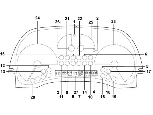
- vehicle speed (speedometer);
- mileage (milometer display with total and trip mileage);
- fuel level (gauge and reserve warning light);
- clock (hours and minutes) (integrated in the milometer display);
- warning lights
- headlamp alignment corrector with two buttons (display of control position).
BASIC VERSION (STANDARD CARGO, STANDARD PANORAMA)
SPEEDOMETER (C1)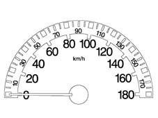
BASIC VERSION (STANDARD CARGO, STANDARD PANORAMA)
I.L.B. INDICATOR (E1)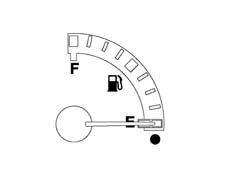
BASIC VERSION (STANDARD CARGO, STANDARD PANORAMA)
LCD (G1)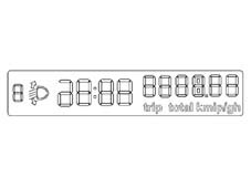
SUPER VERSION (ELEGANT VAN, ELEGANT PANORAMA)
like the basic version with the addition of:
- engine rpm (rev counter);
- coolant temperature (gauge and overheating warning light);
- warning lights
- trip computer with LCD display of trip mileage, range, average speed, journey time and average consumption.
SUPER VERSION (ELEGANT VAN, ELEGANT PANORAMA)
SPEEDOMETER (C3)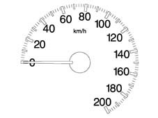
SUPER VERSION (ELEGANT VAN, ELEGANT PANORAMA)
REV COUNTER (D1)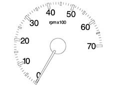
SUPER VERSION (ELEGANT VAN, ELEGANT PANORAMA)
I.L.B. INDICATOR (E2)
SUPER VERSION (ELEGANT VAN, ELEGANT PANORAMA)
COOLANT TEMPERATURE GAUGE (F1)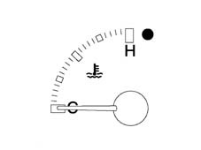
SUPER VERSION (ELEGANT VAN, ELEGANT PANORAMA)
LCD (G1)
COMPONENTS AND OPERATION
The main components of the instrument panel feature:
- External scale in white and internal scale in red and sector in grey (excluding de-luxe versions);
- Serigraphy lighting and indexes in orange.
- Rev counter (petrol and diesel) without danger zone.
- Coolant temperature gauge with danger area in red.
- LCD always lit up in orange.
- Warning lights.
LCD:
The following are displayed on the LCD DISPLAY:
- clock
- headlamp position
- six figures with seven segments for the milometer
- four figures for the trip meter.

LCD:
All the information from and for the instrument panel is transferred, through the CAN interface at low speed, with the exception of data expressly indicated in the pin out. The fault diagnosis is also carried out through the CAN line.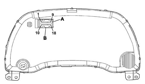
LCD:
A single AMO MQS 18-way vertical connector is used.PIN OUT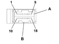
Direct inputs
List of direct input signals:
- + 15 key;
- + battery;
- + lights from dimmer;
- Air Bag failure warning light (only for versions with Air Bag);
- Passenger Air Bag disabled warning light (only for versions with Air Bag);
- Seat belt warning light for Japanese version only;
- CAN line;
- Dipped headlamps signal for headlamp alignment;
Network direct inputs
List of direct input signals:
- Vehicle speed;
- RPM
- Fuel level;
- Fuel consumption
- Coolant temperature
- Mileometer;
- Warning lights
- Network management messages.
Direct outputs
List of direct output signals:
- Headlamp alignment signal;
- Oil level sensor operation;
Network output
- Network management messages and NQS operaton.GENERAL DESCRIPTION
The programming (in the production plant) is carried out with a special instrument, on the vehicle assembly line, using the CAN serial line.The Instrument Panel Connector (NQS) receives all the configuration parameters with a single Fiat EOL (end of line) command. The Instrument Panel therefore memorizes the data.EOL PROGRAMMING
The Instrument Panel Connector (NQS) described so far uses four basic electronic fittings common to all versions, the difference being in the reception of the configuration parameters. If the NQS is replaced in the service network it is configured using the diagnostic equipment (SDC Examiner).If any one of the connectors is not correctly configured or if the various connectors have been configured using incompatible data, then the Instrument Panel display segments used will flash at a frequency of 1 Hz, duty cycle 50%.This procedure is necessary to signal the failed or incomplete personalization of one of more connectors for the CAN network on the vehicle following replacement operations in the service network.NQS PROGRAMMING
The following Instrument Panel Connector (NQS) parameters are personalized, according to the version:
- Tank capacity according to the version (Diesel / Petrol);
- Tank percentage which activates the reserve warning light;
- Oversize percentage in the vehicle speed reading;
- ABS;
- Diesel/Petrol version;
- Right/left hand drive.
| If the instrument panel does not accept the configuration in the service network, it is necessary to make sure that the product code is correct. |
MILOMETER
View of milometer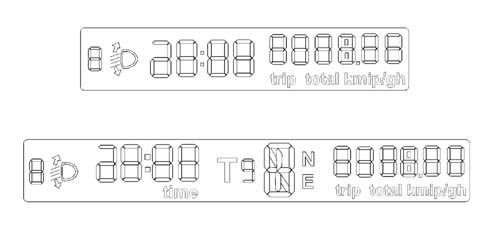
MILOMETER
The NQS receives information on the journey distance, via the CAN line, from the Body Computer. This information corresponds to a counter value which is increased by one unit each time 10m is travelled.For every 10 counter values the trip meter is increased and therefore every 1000 metres, the total mileage is increased by 1 km.The internal microprocessor converts the value received at the CAN network from km to miles using a suitable algorhythm.The NQS memorizes the journey data in kilometres and only converts them into miles during the display. The limit for the trip meter remains 999.9 for both the km and miles, whilst the total limit is in kilometres only (399999) equal to around 248,547 miles.| When the limit (399999 km) is exceeded, the display shows 5 dashes at the centre and in place of the figures. |
CLOCK
The clock is shown in the same display as the milometer and is located between the headlamp alignment reading and the milometer figures; the reading is in hours and minutes and goes from 00.00 to 23.59. Each time the battery is connected the clock shows 00:00.The two dots between the hours and the minutes flash every second.The clock adjustment button is in the instrument panel. When it is pressed, the clock adjustment takes place as follows:
- Pressing the button for 0.1 seconds produces an increase of one minute;
- Pressing the button for between 1 and 3 seconds increases the minutes at an increasing speed which varies in a linear manner starting from an increase of 1 minute every 0.5 seconds, up to an increase of 1 minute every 0.2 seconds.
- Continuing to keep the button pressed for longer than 3 seconds causes an increase in 10 minute steps (rounded off to the next ten);
SPEEDOMETER
The instrument panel receives speed information via the CAN line. The value received in this way is increased for the EOF value programmed and is then displayed on the graduated scaleThe calculation error for values expressed in miles (milometer and speedometer) is less than 0.1 %. The panel configuration is for operation in miles. This parameter is only modified at the Magneti Marelli EOL (end of line).The Instrument Panel Connector receives the engine rpm informtion, directly from the engine management control unit and without corrections the panel processes the engine rpm data with a constant time so that the response at zero RPM - end of scale RPM is less than 2 seconds.INDICATOR RECOVERY LOGICS (STEPPING MOTOR)
The recovery of any steps which may be lost by the instrument is guaranteed for each individual indicator. The ''return to zero'' logic for the indicators occurs for every battery disconnecting / reconnecting operation. An (automatic) ''return to zero'' logic is us| ... DATA ERROR - CROPPED TEXT | Ошибка данных - Текст обрезан ... |
|---|