939010735 - 2110B34 MANUAL GEARBOX (6 SPEED) WITH DIFFERENTIAL - DISMANTLING AND REASSEMBLY - WASH, CHECK COMPONENTS, REPLACE SYNCHRONIZERS AND INTERNAL CONTROLS
| Two mechanics are needed for this operation. |
| Description | Code | Function | |
|---|---|---|---|
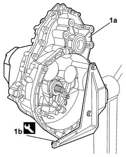
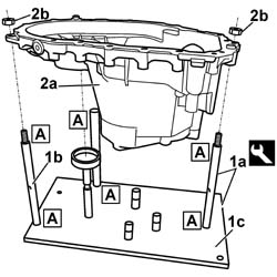
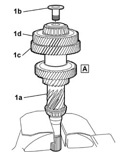
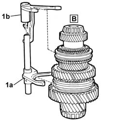
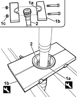
| 1b | Support | 1.871.001.014 | Support for gearbox on overhaul stand |
| Description | Code | Function | |
|---|---|---|---|
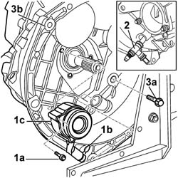
| 2 | Blade | 1.870.718.000 | Removing gearbox casing-clutch casing sealant |
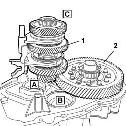
| Keep the assemblies joined until they are resting on the workbench. |
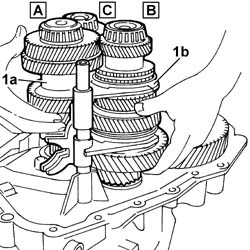
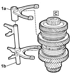
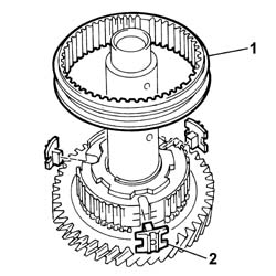
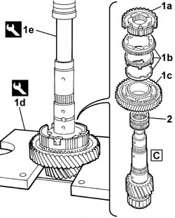
| To allow quick identification, each shaft is given a corresponding letter: main shaft (A), first layshaft (B) and second layshaft (C), as shown in the diagram. |
| The identification letters for the position of the pins are on the plate for the support tool; position (A) should be used for the gearbox casing support, positions (B) and (C) should be used for the clutch casing support. |
| Description | Code | Function | |
|---|---|---|---|
| 1st | Gearbox casing/ clutch casing support | 1.870.897.700 | Gearbox casing support for determining bearing pre-loading |
| The operation of removing the lubrication ducts destroys them, therefore new parts must be used when refitting. |
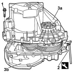
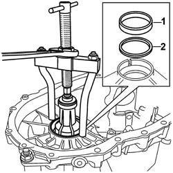
| To facilitate recognizing the seats for each of the shafts, the main shaft seat is identified in the diagram by the letter (A), the first layshaft seat by the letter (B) and the second layshaft seat by the letter (C). The extraction operation is the same for all three rear bearing outer races. |
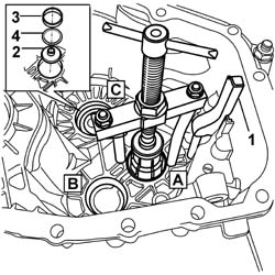
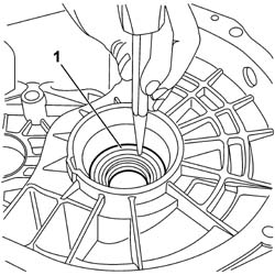
| To facilitate recognizing the seats for each of the shafts, the main shaft seat is identified in the diagram by the letter (A), the first layshaft seat by the letter (B) and the second layshaft seat by the letter (C). The extraction operation is the same for all three front bearing outer races. |
| Description | Code | Function | |
|---|---|---|---|
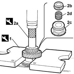
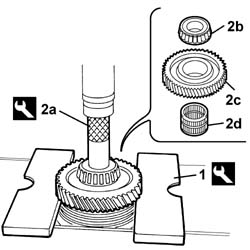
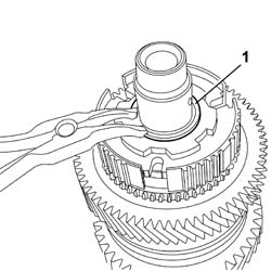
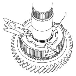
| 1 | Half plate | 1.860.837.000 | Dismantling main shaft |
| The main shaft (A) should be supported at the bottom during this operation. |
| Description | Code | Function | |
|---|---|---|---|
| 2nd | Reaction pin | 1.870.899.100 | Dismantling main shaft |
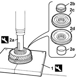
| The main shaft (A) should be supported at the bottom during this operation. |
| Description | Code | Function | |
|---|---|---|---|
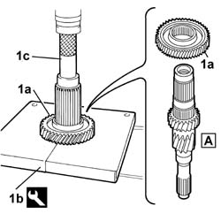
| 1b | Half plate | 1.860.837.000 | Dismantling main shaft |
| Description | Code | Function | |
|---|---|---|---|
| 1c | Reaction pin | 1.870.899.100 | Dismantling main shaft |
| Description | Code | Function | |
|---|---|---|---|
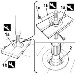
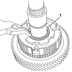
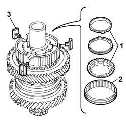
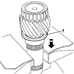
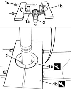
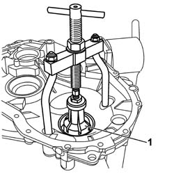
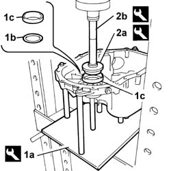
| 1a | Extraction half-rings | 1.870.899.200 | Extracting main shaft front bearing |
| Description | Code | Function | |
|---|---|---|---|
| 1b | Extractor | 1.870.845.100 | Extracting main shaft front bearing |
| The main shaft (A) should be supported at the bottom during this operation. |
| Description | Code | Function | |
|---|---|---|---|
| 1 | Half plate | 1.860.837.000 | Dismantling layshaft (B) |
| The layshaft (B) should be supported at the bottom during this operation. |
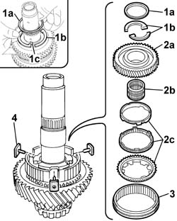
| Description | Code | Function | |
|---|---|---|---|
| 2a | Reaction pin | 1.870.899.100 | Dismantling main shaft |
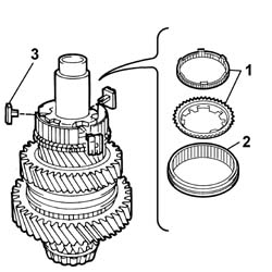
| When refitting, replace the circlip. |
| Description | Code | Function | |
|---|---|---|---|
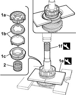
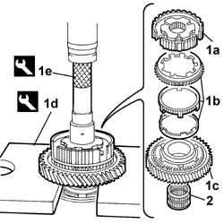
| 1e | Half plates | 1.870.899.400 | Extracting 5-6th speed sliding sleeve hub |
| Description | Code | Function | |
|---|---|---|---|
| 1f | Reaction pin | 1.870.899.100 | Dismantling layshaft (B) |
| The layshaft (B) should be supported at the bottom during this operation. |
| When refitting, replace the circlip. |
| Description | Code | Function | |
|---|---|---|---|
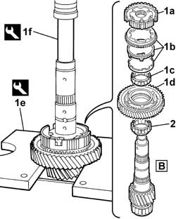
| 1e | Half plates | 1.860.837.000 | Extracting hub for 1st-2nd speed sliding sleeve |
| Description | Code | Function | |
|---|---|---|---|
| 1f | Reaction pin | 1.870.899.100 | Dismantling layshaft (B) |
| The layshaft (B) should be supported at the bottom during this operation. |
| Description | Code | Function | |
|---|---|---|---|
| 1a | Extraction half-rings | 1.870.899.600 | Extracting layshaft front bearing (B) |
| Description | Code | Function | |
|---|---|---|---|
| 1b | Extractor | 1.870.845.100 | Extracting layshaft front bearing (B) |
| The layshaft (B) should be supported at the bottom during this operation. |
| Description | Code | Function | |
|---|---|---|---|
| 1 | Half plates | 1.870.899.400 | Dismantling layshaft (C) |
| The main shaft (A) should be supported at the bottom during this operation. |
| Description | Code | Function | |
|---|---|---|---|
| 2a | Reaction pin | 1.870.899.100 | Dismantling layshaft (C) |
| When refitting, replace the circlip. |
| Description | Code | Function | |
|---|---|---|---|
| 1d | Half plates | 1.860.837.000 | Extracting hub for 3rd-4th speed sliding sleeve |
| Description | Code | Function | |
|---|---|---|---|
| 1e | Reaction pin | 1.870.899.100 | Dismantling layshaft (C) |
| The layshaft (C) should be supported at the bottom during this operation. |
| Description | Code | Function | |
|---|---|---|---|
| 1a | Extraction half-rings | 1.870.899.700 | Extracting spacer on layshaft (C) |
| Description | Code | Function | |
|---|---|---|---|
| 1b | Extractor | 1.870.845.100 | Extracting spacer on layshaft (C) |
| The layshaft (C) should be supported at the bottom during this operation. |
| Description | Code | Function | |
|---|---|---|---|
| 2b | Reaction pin | 1.870.899.100 | Dismantling layshaft (C) |
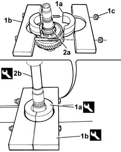
| When refitting, replace the circlip. |
| Description | Code | Function | |
|---|---|---|---|
| 1d | Half plates | 1.860.837.000 | Extracting hub for reverse gear sliding sleeve |
| Description | Code | Function | |
|---|---|---|---|
| 1e | Reaction pin | 1.870.899.100 | Dismantling layshaft (C) |
| The layshaft (C) should be supported at the bottom during this operation. |
| Description | Code | Function | |
|---|---|---|---|
| 1a | Extraction half-rings | 1.870.899.500 | Extracting layshaft front bearing (C) |
| Description | Code | Function | |
|---|---|---|---|
| 1b | Extractor | 1.870.845.100 | Extracting layshaft front bearing (C) |
| The layshaft (C) should be supported at the bottom during this operation. |
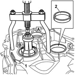
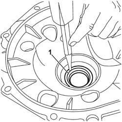
| The operation of removing the seal destroys it, therefore a new seal is required when refitting. |
| The operation of removing the seal destroys it, therefore a new seal is required when refitting. |
| Description | Code | Function | |
|---|---|---|---|
| 1a | Gearbox casing/ clutch casing support | 1.870.897.700 | Gearbox casing support for determining bearing pre-loading |
| Description | Code | Function | |
|---|---|---|---|
| 2a | Drift | 1.870.898.500 | Fitting differential rear bearing outer race |
| Description | Code | Function | |
|---|---|---|---|
| 2b | Grip | 1.870.898.400 | Fitting differential rear bearing outer race |
| Description | Code | Function | |
|---|---|---|---|
| . | Gearbox casing/ clutch casing support | 1.870.897.700 | Gearbox casing support for determining bearing pre-loading |