199000400 - 1004B10 POWER UNIT WITH MANUAL GEARBOX - R.R
| Tool | Description | Function | Validity |
|---|---|---|---|
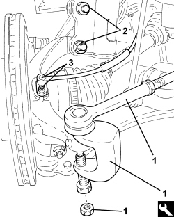
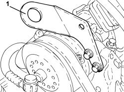
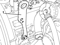
| 1871000700 | Extractor | Extracting steering rod from strut |
| Tool | Description | Function | Validity |
|---|---|---|---|
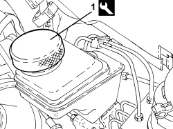
| 2000001400 | Plug | Brake/ clutch system vacuum |
| Description | Connector | |
|---|---|---|
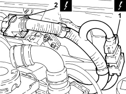
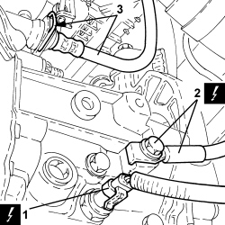
| 1 | Engine cables/engine services cable coupling | See D029 ENGINE CABLES/ENGINE SERVICES CABLE COUPLING |
| Description | Connector | |
|---|---|---|
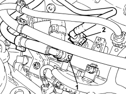
| 2 | Engine management control unit | See M010 ENGINE MANAGEMENT ECU |
| Description | Connector | |
|---|---|---|
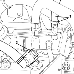
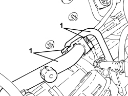
| 1 | Reversing light switch | See I020 REVERSING LIGHTS SWITCH (GEARBOX BRIDGE) |
| Description | Connector | |
|---|---|---|
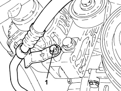
| 2 | Battery earth on engine | See C002 BATTERY EARTH ON ENGINE |
| Tool | Description | Function | Validity |
|---|---|---|---|
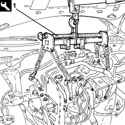
| 1871001700 | Balance | Removing/ refitting power unit |
| Component | Fastening | dia | Value (daNm) | Validity |
|---|---|---|---|---|
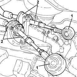
| Front shock absorber - strut side | Bolt (to be replaced) | M12 | 10.3 ÷ 12.6 + 45° |
| Component | Fastening | dia | Value (daNm) | Validity |
|---|---|---|---|---|
| Steering rod to pillar | Nut | M10 | 3.6 ÷ 4.4 |